Van Laser-Cut naar Assembly-Ready — Automatisch.
Lasersnijden is nauwkeurig. Maar elk onderdeel dat de machine verlaat heeft nog steeds bramen, oxide, slakken en scherpe randen — en het oppervlak moet nog worden bewerkt voordat het kan worden gecoat, gelast of geassembleerd. Handmatig ontbramen lost dit langzaam, inconsistent en tegen hoge arbeidskosten op. Geautomatiseerde afwerkingsmachines lossen dit op in één enkele, herhaalbare procedure — in lijn met uw bestaande laserproductielijn.
Eén operator verwerkt wat voorheen meerdere handmatige slijpstations nodig had
Ontbramen, oxideverwijdering, randafronding en oppervlakteafwerking — alles in één transportproces

Problemen waarmee elke lasershop na elke snede wordt geconfronteerd
Lasersnijden is snel en nauwkeurig, maar het maakt het onderdeel niet af. Elk werkstuk dat uw lasersnijder verlaat, heeft nog steeds deze typische defecten.
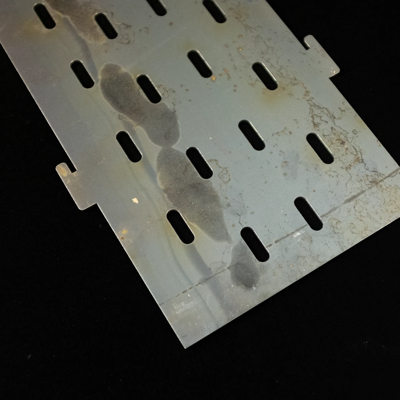
Oxidelaag en hittetint
Lasersnijden — vooral CO₂ en vezels met zuurstofondersteuning — vormt een donkere oxidefilm rond elke snijkant. Op koolstofstaal is het een dikke, broze laag. Op roestvrij staal is het een verkleurde hittetint. Beide blokkeren de lashechting, verstoren de hechting van verf en poedercoating en veroorzaken voortijdige corrosie.

Bramen en slakken
Lasersnijden laat op elke snijkant ongewenst metaal achter — de vorm is afhankelijk van de dikte. Op het standaardblad is het resultaat bramen: verticale uitsteeksels boven het snijvlak en zijdelingse uitsteeksels die zich zijwaarts uitspreiden. Op een dikke plaat van meer dan 6—8 mm smelt door de hitte meer materiaal dan de snede uitwerpt, dat opnieuw stolt als het uitgehard wordt slak aan de onderzijde. Standaard ontbraamgereedschap slijt snel tegen slakken en kan dit niet op dezelfde manier behandelen als bramen.
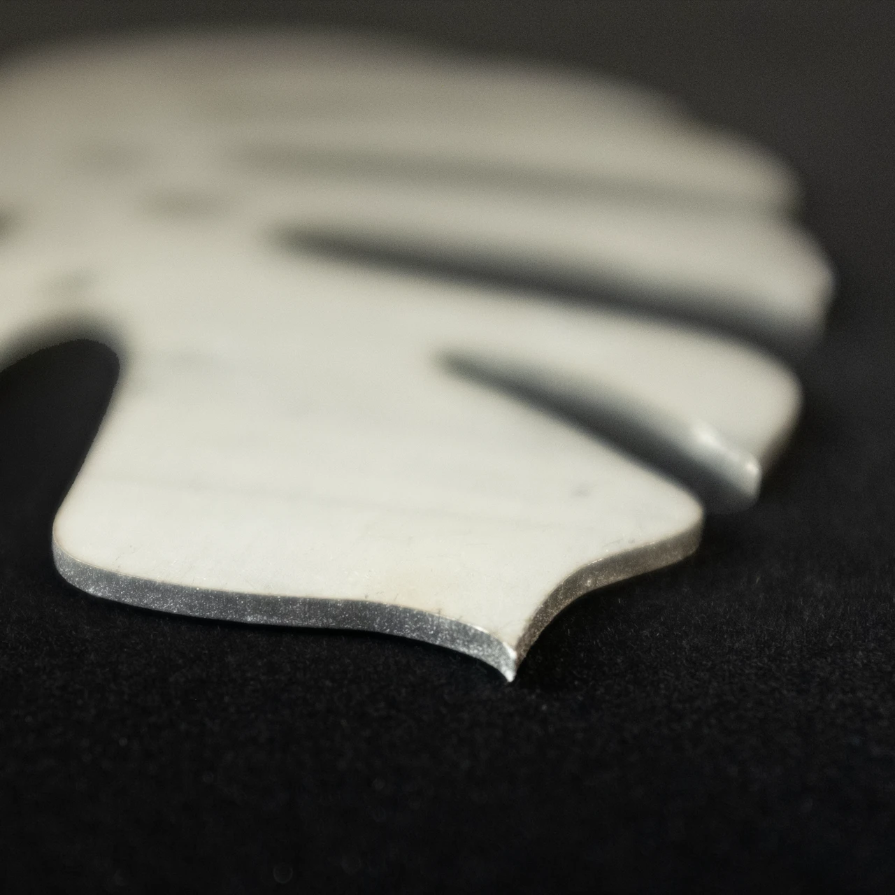
Scherpe randen en inconsistente radius
Zelfs een zuivere lasersnede laat messcherpe hoeken achter op elk profiel en elke interne uitsparing. Coatings worden dunner bij scherpe randen als gevolg van oppervlaktespanning — daar beginnen roest en afbladderen. Handmatig slijpen lost dit op, maar de resultaten variëren per operator en per ploegendienst. OEM's en Tier-1-leveranciers hebben steeds vaker een gedefinieerde, gedocumenteerde randradius nodig voor coatingspecificaties en PPAP.
Voer uw onderdelen door voordat u een beslissing neemt
Deel uw materiaal, dikte en geometrie van uw onderdelen — onze ingenieurs brengen de juiste machine in kaart en kunnen een test uitvoeren met uw werkelijke onderdelen. Bekijk de randradius en oppervlakteafwerking voordat u zich vastlegt.

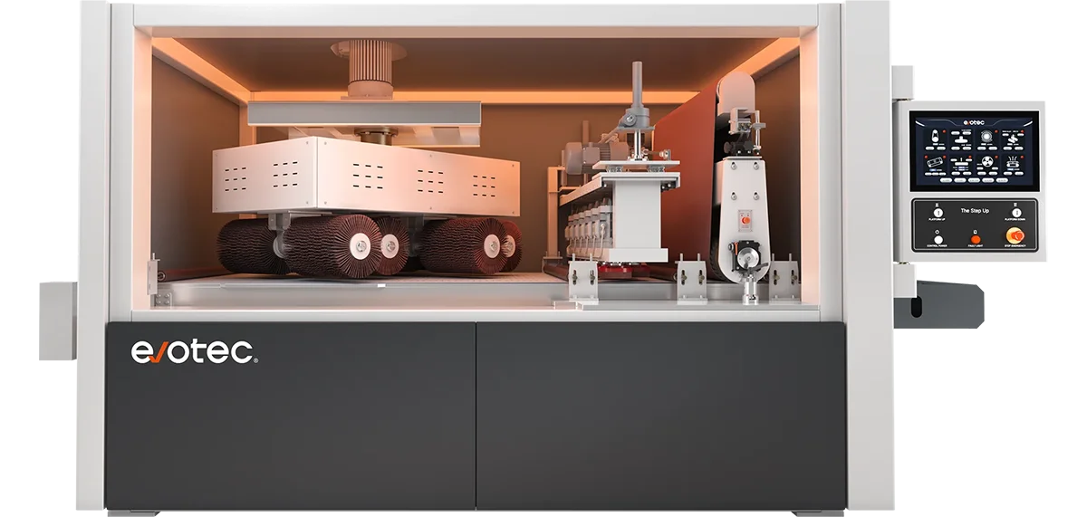
Wat elke afwerkingsstap doet voor lasergesneden onderdelen
Het afwerken van een lasergesneden onderdeel omvat verschillende processen, die elk gericht zijn op een ander defect dat door de snede is achtergelaten. De meeste geautomatiseerde ontbraammachines combineren meerdere fasen in één werkgang. Als u begrijpt wat elk proces doet — en wat er stroomafwaarts gebeurt wanneer het wordt overgeslagen — is het eenvoudiger om de juiste configuratie te kiezen.
01. Ontbramen
Elke lasersnede laat verticale en laterale bramen achter op de snijrand. Ze voorkomen dat onderdelen vlak in de armaturen zitten en beschadigen alle stroomafwaartse precisie-apparatuur waarmee ze in contact komen.

02. Verwijdering van laseroxide
Zuurstofondersteund snijden vormt een oxidelaag langs de snijkant — een donkere film op koolstofstaal, een hittetint op roestvrij staal. Beide blokkeren de hechting van de coating en introduceren lasporositeit.

03. Slakken verwijderen
Op een dikke plaat van meer dan ~ 6-8 mm stolt overtollig gesmolten metaal opnieuw als geharde slak op de gesneden onderkant. Standaard schuurbanden slijten snel en kunnen deze niet op betrouwbare wijze verwijderen.

04. Randafronding
De snijkanten zijn ook na het ontbramen geometrisch scherp. Coatings worden dunner in scherpe hoeken — daar begint roest. Randafronding zorgt voor een gecontroleerde radius van R0.3 tot R2.5+ over alle contouren.
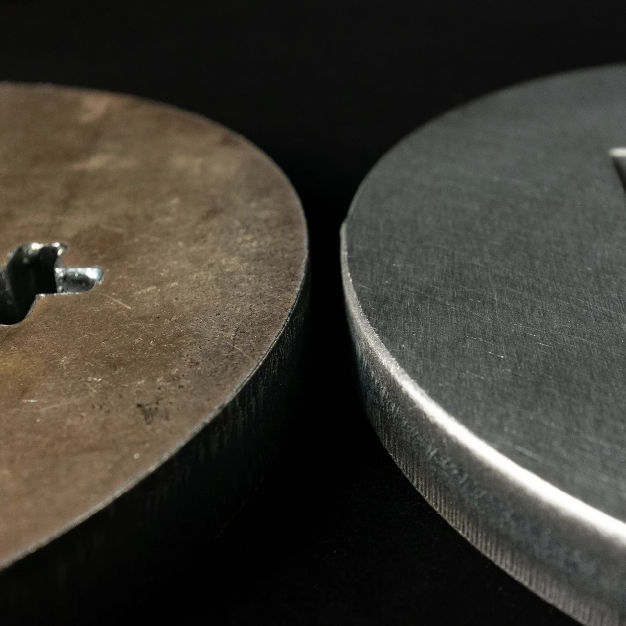
05. Oppervlakteafwerking
Twee opties: niet-directioneel (willekeurige werveling) voor onderdelen die worden gecoat of gelast — geen zichtbare korrel, betere hechting. Lijnkorrel voor zichtbare architecturale of decoratieve toepassingen waarbij de geborstelde textuur deel uitmaakt van de specificatie.

Meest geselecteerde configuraties voor verschillende klantprojecten
Deze configuraties worden vaak door klanten geselecteerd op basis van typische vereisten voor plaatbewerking. Elk model combineert specifieke verwerkingsmodules voor veelgebruikte toepassingen zoals ontbramen, randafronding, oppervlakteafwerking en polijsten.
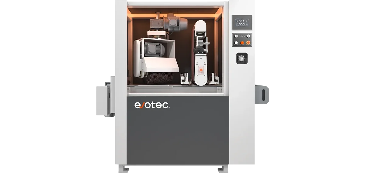
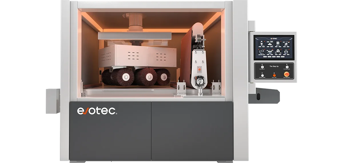


Alle modellen, naast elkaar
Elke machine verwerkt roestvrij staal, koolstofstaal, aluminium en messing. Ze ondersteunen allemaal de add-on Wet Extraction. Min. werkstuk 50 × 50 mm voor alle modellen.
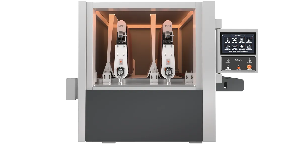
Aanpassing Capaciteiten
Evotec-machines bieden een reeks configureerbare opties, waardoor fabrikanten hun apparatuur kunnen aanpassen aan specifieke verwerkingsbehoeften. Van stofafzuiging tot modulaire schuurconfiguraties, elke aanpassing verbetert de prestaties en optimaliseert de efficiëntie van de workflow.
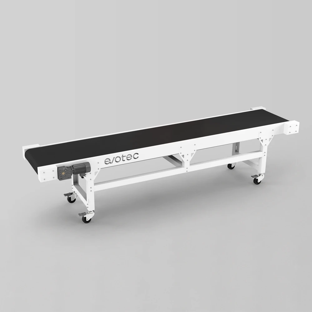
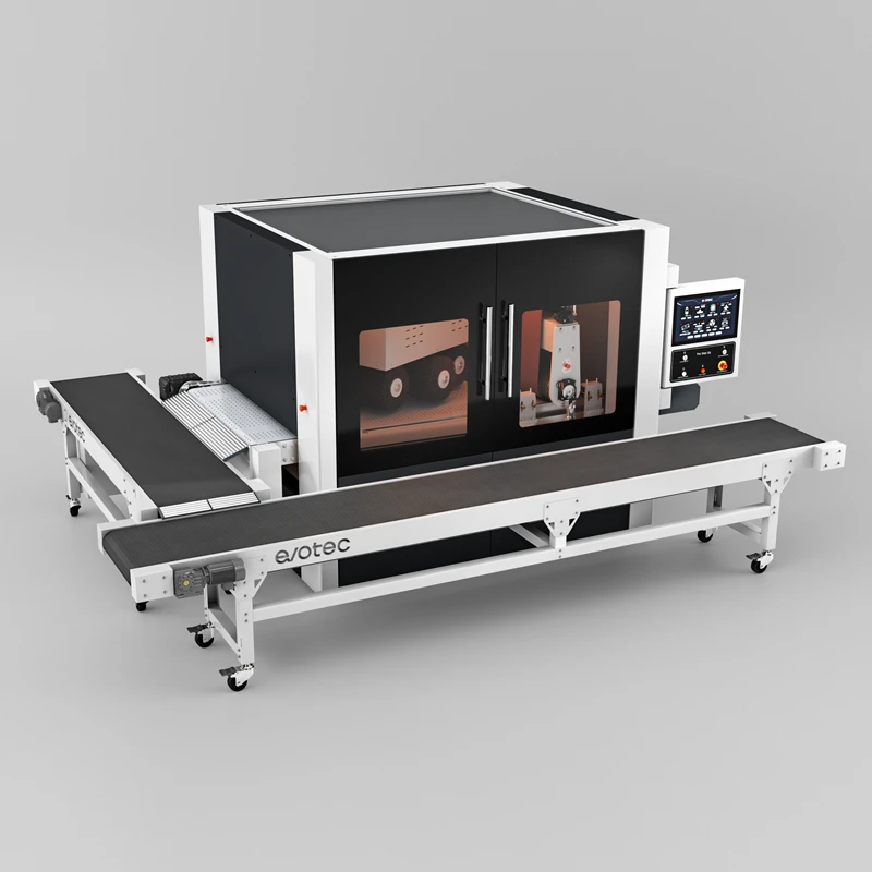
TRANSPORTBAND
De CONVEYOR van Evotec automatiseert de invoer- en uitvoerverwerking voor uw Evotec-afwerkingslijn. Beschikbaar in invoer- en uitvoerconfiguraties met een breedte van 800, 1300 en 1600 mm.
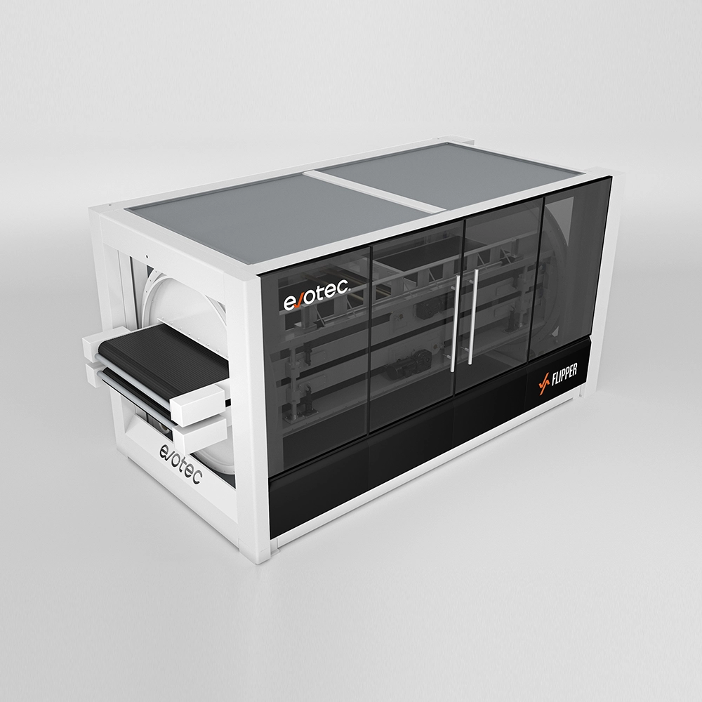
Flipper
De geautomatiseerde oplossing voor dubbelzijdige afwerking — aan beide zijden, in één keer, zonder handmatig omdraaien.
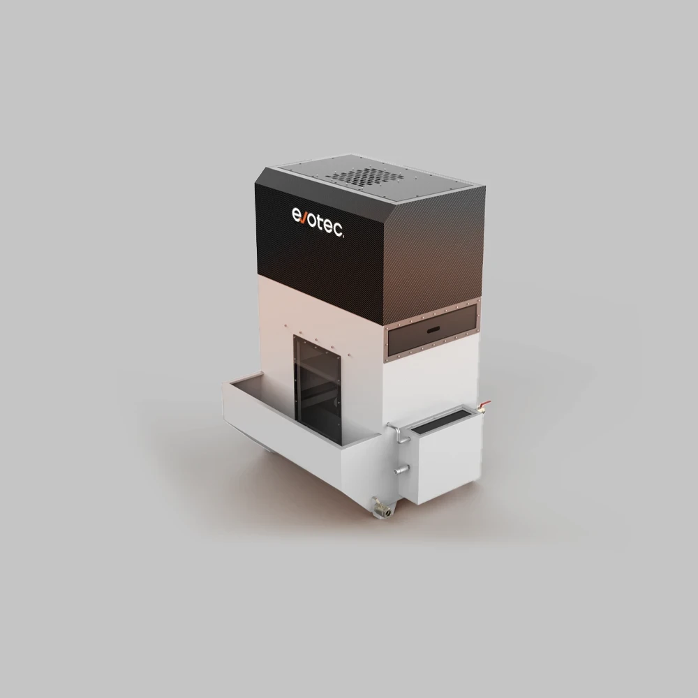
Hydro Dust 2.0
Nat afzuigsysteem dat metaalstof veilig verwijdert tijdens de afwerking.
U-Flow
Geautomatiseerde retourtransporteur die een efficiënte dubbelzijdige afwerking van onderdelen mogelijk maakt.
Ontvang een configuratieaanbeveling
Het kiezen van het juiste product is een uitdaging, maar we zijn er om u te helpen. Met meer dan tien jaar ervaring in de automatiseringsindustrie voor ontbramen en randafronding hebben we het allemaal gezien.
Veelgestelde vragen
Een lasersnede kan er voor het oog glad uitzien, terwijl er nog steeds microscopische bramen langs de snijranden, messcherpe hoeken op elk profiel en — met name op koolstofstaal — een zichtbare oxidelaag rond de snijzone aanwezig zijn. Deze defecten zijn inherent aan het thermische snijproces en kunnen niet worden voorkomen door alleen de laserparameters aan te passen. Ontbramen en randafwerking hebben betrekking op wat de lasersnijder niet kan: de toestand van het onderdeel na het snijden. Zonder afwerking vormen onderdelen veiligheidsrisico's tijdens het gebruik, zitten ze niet vlak in buig- of lasarmaturen en veroorzaken ze fouten in de hechting van de coating nadat ze zijn geverfd of gepoedercoat.
Wanneer een laser koolstofstaal snijdt — met name met zuurstofgas — of roestvrij staal snijdt, vormt zich langs de snijkant een metaaloxidelaag als bijproduct van de warmte. Op koolstofstaal verschijnt dit oxide als een donkere, broze film. Op roestvrij staal wordt dit weergegeven als een blauwe, gouden of bruine hittetint. Beide vormen van oxide voorkomen dat poedercoatings en verf zich goed hechten aan het metalen oppervlak, en ze zorgen voor porositeit in lassen die op of nabij de snijkant worden gemaakt. Laseroxideverwijdering, uitgevoerd met behulp van schuurband- en borstelcombinaties op de afwerkingsmachine, stript deze laag en herstelt kaal, reactief metaal. Dit is een vereiste stap voor elk lasergesneden onderdeel dat dicht bij de snijrand wordt gepoedercoat, nat geverfd of gelast.
De minimale randradius die wordt aanbevolen voor gepoedercoate onderdelen is doorgaans R0,3—R0,5 mm op blootgestelde randen. Dit is voldoende om de coating op de hoek tot een voldoende laagdikte op te bouwen zonder uit te dunnen. Voor onderdelen die buitenshuis, in corrosieve omgevingen of onder de vereisten voor zoutsproeitests worden gebruikt, wordt gewoonlijk R1.0 tot R2.5+ gespecificeerd. Grotere radii zorgen ervoor dat poeder zich effectiever om de hoek kan wikkelen, waardoor een dikkere, duurzamere film aan de rand ontstaat — wat ook het meest kwetsbare punt is voor roestvorming. Als uw eindklant of OEM een gedefinieerde coatingspecificatie heeft, vermelden ze doorgaans een minimale rantradius. Als er geen specificatie bestaat, is R0.5 een redelijke basis voor algemene fabricage.
Niet-directionele afwerking, ook wel random swirl of NDMF genoemd, wordt geproduceerd door roterende borstelmodules die het oppervlak in meerdere richtingen tegelijk bewerken, waardoor een consistente textuur ontstaat zonder een zichtbare korrelrichting. Dit is de standaardafwerking voor onderdelen die worden gecoat, gelast of geassembleerd — het consistente oppervlakteprofiel verbetert de hechting van de coating gelijkmatig over het oppervlak zonder richtingmarkeringen te introduceren die door een dunne coating zichtbaar zouden zijn. De afwerking met lijnnerf wordt bereikt door schurende trommelkoppen die in één richting bewegen, waardoor een uniform richtingspatroon ontstaat dat vergelijkbaar is met het geborstelde roestvrij staal dat wordt gebruikt in architecturale panelen, keukenapparatuur of zichtbare industriële behuizingen. Het wordt meestal gespecificeerd voor cosmetische of architecturale toepassingen waarbij de geborstelde textuur deel uitmaakt van het uiterlijk van het eindproduct. De meeste structurele en geverfde lasergesneden onderdelen maken gebruik van een niet-directionele afwerking.
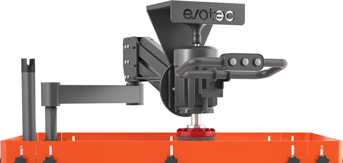
De standaard configuraties van de trommelkop en de roterende borstel zijn zeer goed bestand tegen externe perimeters. Voor interne functies — gaten, sleuven, openingen en complexe uitsparingen — hebt u bovenborstelmodules nodig (eenheid D). Dit zijn fijne, vingerachtige penselen die zich een weg banen naar de interne contouren van het onderdeel, waarbij zijdelingse bramen aan de binnenranden worden verwijderd en de binnenomtrek wordt afgerond. De EdgeX SDR is het model dat speciaal hiervoor is ontworpen: de configuratie in drie fasen (drumkop → bovenborstels → roterende borstels) zorgt ervoor dat de externe en interne randafronding in dezelfde gang worden afgerond. Het is gevalideerd om R2.5+ op randen te bereiken. Onderdelen met boutgaten, rechthoekige sleuven of complexe uitsparingspatronen profiteren het meest van deze configuratie.
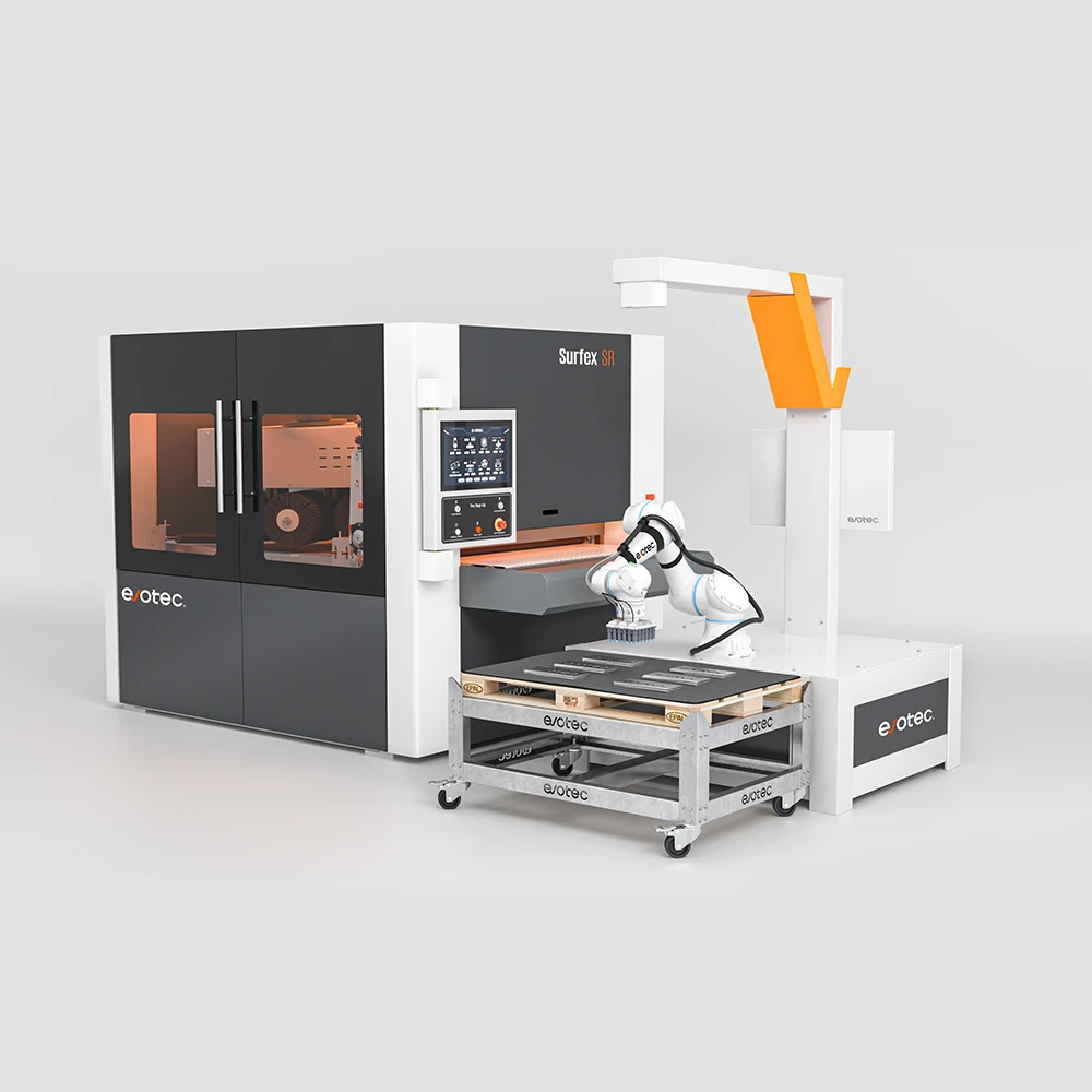
De afwerkingsmachines van Evotec zijn ontworpen om inline te werken — direct na de lasersnijder in de productiestroom geplaatst. De machine ontvangt onderdelen van de laseruitgang, doorloopt ze door de geconfigureerde afwerkingsfasen (uitgebreide transportsystemen en de VSORT vision-guide robo-arm zijn nodig om automatisch onderdelen te laden en te lossen), en levert afgewerkte onderdelen naar de volgende stap. Voor kleinere winkels worden compacte modellen zoals de FabGo 300 of FabGo 600 direct naast de lasersnijder geplaatst met een minimale voetafdruk. Voor operaties met een groter volume kan de volledige SurfEx- en EdgeX-serie worden aangesloten op de productielijn en kan deze worden uitgebreid met de geautomatiseerde VSORT-lader (voor handsfree invoer van onderdelen), de U-Flow-retourtransporteur (voor dubbelzijdige afwerking met één operator) en de Flipper (voor automatisch omdraaien van onderdelen). De machines maken gebruik van het EvoFlow-transportsysteem met vacuüm- (AirLock) of magnetische (MagniLock) werkstukbevestiging (MagniLock), dat onderdelen verwerkt die zo klein zijn als 50 × 50 mm. Er is geen speciale bevestiging of aangepaste integratie vereist.
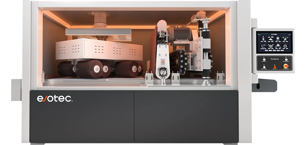
Ja, dat is precies het voordeel van geautomatiseerde afwerkingsmachines ten opzichte van handmatige processen. De machines van Evotec zijn modulair: meerdere bewerkingskoppen (trommelkoppen, roterende borstels, bovenborstels, polijststaaf, slaghamer) zijn achter elkaar op dezelfde transportband gerangschikt. Een deel dat aan het ene uiteinde wordt ingevoerd, verlaat het andere wanneer alle geconfigureerde processen zijn voltooid. De SurfEx SRS-configuratie laat bijvoorbeeld een onderdeel in één keer door een drumvel (ontbramen + oxideverwijdering), roterende borstels (randafronding) en een tweede drumvel (lijnkorrelafwerking) lopen. De EdgeX SDR bestaat uit een trommelkop, bovenborstels (interne afschuining) en roterende borstels (randafronding + NDMF-afwerking). De machineconfiguratie wordt bij de bestelling gekozen op basis van de processen die uw onderdelen nodig hebben — u bent niet beperkt tot één proces per machine.
Heb je nog vragen?
Voer uw onderdelen door voordat u een beslissing neemt
Deel uw materiaal, dikte en geometrie van uw onderdelen — onze ingenieurs brengen de juiste machine in kaart en kunnen een test uitvoeren met uw werkelijke onderdelen. Bekijk de randradius en oppervlakteafwerking voordat u zich vastlegt.